Hardware
The LC29H GPS/RTK HAT is a 65mm x 30.5mm board that connects the Quectel LC29H dual-band GNSS module to single-board computers via the 40-pin GPIO header. This page covers every physical aspect of the board: connection methods, jumper configuration, LED behavior, GPIO mapping, power requirements, and antenna guidance.
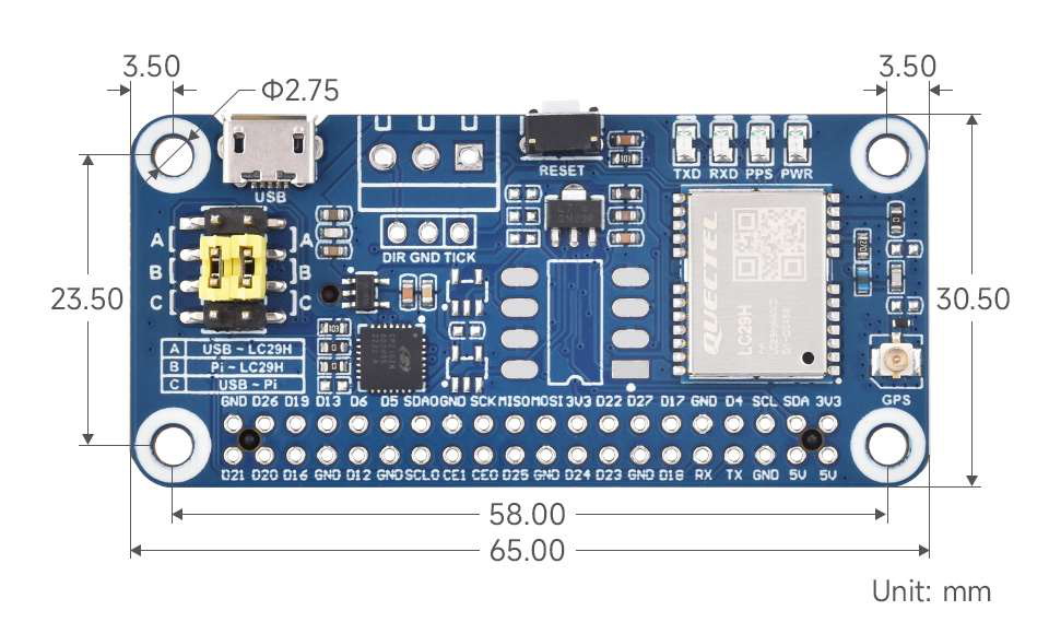 Board layout showing jumper positions A/B/C, LED indicators, GPIO header, RESET button, and IPEX antenna connector. Image: Waveshare
Connection Methods
Section titled “Connection Methods”Three ways to connect the HAT to a host, depending on your hardware and use case.
| Method | Device Path | Baud Rate | GPIO Required | Best For |
|---|---|---|---|---|
| HAT (direct stack) | /dev/ttyS0 (Pi 4B) or /dev/ttyAMA0 (Pi 5) | 9600 default, typically configured to 115200 | Yes (UART) | Raspberry Pi, Jetson Nano |
| USB cable | /dev/ttyUSB0 | 9600 default, typically configured to 115200 | No | Any computer with USB |
| Jumper wires to GPIO | Depends on host UART device | 9600 default, typically configured to 115200 | Yes (wired) | Non-Pi SBCs, breadboard prototyping |
HAT (Direct Stack on Pi GPIO)
Section titled “HAT (Direct Stack on Pi GPIO)”The simplest method for Raspberry Pi and Jetson Nano. Stack the HAT onto the 40-pin header, set the jumper to position B, and the module communicates over the Pi’s hardware UART.
The Pi 4B uses the mini UART at /dev/ttyS0 for GPIO serial by default. Enable it via raspi-config under Interface Options, then Serial Port.
The Pi 5 uses the PL011 UART at /dev/ttyAMA0 for GPIO serial. The device path differs from Pi 4B — double-check your configuration and scripts if migrating between boards.
USB Connection
Section titled “USB Connection”Connect via the onboard micro-USB connector (not USB-C — see the board photo above). Set the jumper to position A. The CP2102N USB-to-UART bridge presents the module as /dev/ttyUSB0. The CP210x kernel driver is included in most modern Linux distributions.
This method requires no GPIO configuration and works with any computer that has a USB port, including laptops running Windows or macOS.
Jumper Wires to GPIO
Section titled “Jumper Wires to GPIO”For SBCs without a Pi-compatible 40-pin header, wire the HAT’s breakout pins directly:
| HAT Pin | Connect To | Notes |
|---|---|---|
| TXD | Host RX pin | Module transmit to host receive |
| RXD | Host TX pin | Host transmit to module receive |
| GND | Host GND | Common ground — required |
| 5V | Host 5V out | Or 3.3V to the 3V3 pin if 5V is unavailable |
Set the jumper to position B when using wired GPIO connections, since the UART lines need to route to the header pins rather than the USB bridge.
Jumper Settings
Section titled “Jumper Settings”The yellow 3-position jumper (visible on the left side of the board) controls how the LC29H module’s UART lines are routed. The three positions are silk-screened directly on the PCB.
| Position | Label on PCB | Routing | Use Case |
|---|---|---|---|
| A | USB - LC29H | Module UART routes through the CP2102N to the micro-USB connector | USB connection to any computer |
| B | Pi - LC29H | Module UART routes directly to the 40-pin GPIO header (GPIO 14/15) | HAT stacked on Pi or wired GPIO |
| C | USB - Pi | USB bridge connects to the Pi UART — the LC29H module is bypassed | Firmware update or USB-to-serial passthrough |
Default position: The HAT ships with the jumper at position B (Pi - LC29H).
Position C explained: This is a special configuration that connects the Pi’s UART directly to the USB bridge, completely bypassing the GNSS module. It is useful for firmware update scenarios where the PC needs a serial passthrough to the module via a separate path.
LED Indicators
Section titled “LED Indicators”Four LEDs along the top-right edge of the board provide status feedback. All LEDs are driven through 1K current-limiting resistors.
| LED | Color | Behavior | Meaning |
|---|---|---|---|
| PWR | Red | Steady on | 5V power is applied to the board |
| TXD | Green | Blinks rapidly | Module is transmitting NMEA sentences to the host |
| RXD | Green | Blinks on activity | Host is sending data (commands, RTCM corrections) to the module |
| PPS | Green | 1 blink per second | Position fix acquired — the module has a valid satellite lock |
Reading the PPS LED
Section titled “Reading the PPS LED”The PPS (Pulse Per Second) output is the most important diagnostic indicator:
- Not blinking: No satellite fix. Check antenna connection, ensure clear sky view, and allow up to 26 seconds for a cold start (or up to 1 second for a hot start if the ML1220 backup battery is charged).
- Blinking once per second: Valid position fix. The module is outputting NMEA sentences with position data.
- Blinking but no position data on serial: Jumper is likely in the wrong position, or the serial port baud rate does not match. The module ships at 9600 baud; the Waveshare sample code reconfigures it to 115200.
RTK Status (DA and BA Variants)
Section titled “RTK Status (DA and BA Variants)”The LC29H(DA) and LC29H(BA) variants support RTK positioning. RTK fix status is not indicated by a dedicated LED on the HAT. Monitor RTK state via the GGA NMEA sentence quality indicator field: 4 = RTK Fixed (centimeter accuracy), 5 = RTK Float (decimeter accuracy).
GPIO Pin Mapping
Section titled “GPIO Pin Mapping”The HAT uses specific pins on the Raspberry Pi 40-pin header. The following table shows the complete mapping.
Primary Communication Pins
Section titled “Primary Communication Pins”| Pi Header Pin | BCM GPIO | Function | Direction | Notes |
|---|---|---|---|---|
| Pin 8 | GPIO 14 (TXD) | UART TX to module RXD | Host to module | Pi transmit, module receive |
| Pin 10 | GPIO 15 (RXD) | UART RX from module TXD | Module to host | Module transmit, Pi receive |
| Pin 3 | GPIO 2 (SDA) | I2C Data | Bidirectional | 4.7K pull-up to 3.3V on board |
| Pin 5 | GPIO 3 (SCL) | I2C Clock | Host to module | 4.7K pull-up to 3.3V on board |
Signal and Control Pins
Section titled “Signal and Control Pins”| Pi Header Pin | BCM GPIO | Function | Direction | Notes |
|---|---|---|---|---|
| Pin 7 | GPIO 4 | PPS (Pulse Per Second) | Module to host | 1 Hz pulse when fix acquired |
| Pin 15 | GPIO 22 | RESET | Host to module | Active low; 10K pull-up to 3.3V on board |
| Pin 11 | GPIO 17 | WAKEUP | Host to module | Toggles module from backup to active mode |
Power Pins
Section titled “Power Pins”| Pi Header Pin | Function | Notes |
|---|---|---|
| Pin 2 or Pin 4 | 5V supply | Powers the HAT via the GPIO header |
| Pin 1 | 3.3V | Not used for power input; the HAT generates its own 3.3V |
| Pin 6, 9, 14, 20, 25, 30, 34, 39 | GND | Common ground |
Breakout Header Pins
Section titled “Breakout Header Pins”The HAT includes breakout pin headers along the top edge (visible in the board photo), providing direct access to signals for wiring or probing:
| Breakout Label | Function |
|---|---|
| TXD | Module UART transmit |
| RXD | Module UART receive |
| PPS | Pulse per second output |
| PWR | Power indicator (active high) |
| DIR | Wheel tick direction input (DR variants: BA, CA) |
| GND | Ground |
| TICK | Wheel tick pulse input (DR variants: BA, CA) |
Pin Functions
Section titled “Pin Functions”| Pin | Function | Description |
|---|---|---|
| RXD | UART Receive | Serial data from host to module |
| TXD | UART Transmit | Serial data from module to host |
| SDA | I2C Data | NMEA 0183 and command transmission via I2C |
| SCL | I2C Clock | I2C clock signal |
| WAKEUP | Wake | Toggles module from backup mode to active |
| PPS | Pulse Per Second | Time synchronization pulse; LED indicates positioning lock |
| WI/RES | Reserved | Not currently available |
Power Requirements
Section titled “Power Requirements”Supply Voltage and Current
Section titled “Supply Voltage and Current”| Parameter | Value | Source |
|---|---|---|
| Input voltage | 5V via GPIO header pin 2/4, or 5V via micro-USB | Wiki, schematic |
| Continuous current draw | < 40 mA at 5V | Wiki specification |
| Operating temperature | -40C to +85C | Wiki specification |
Onboard Voltage Regulation
Section titled “Onboard Voltage Regulation”The HAT has two voltage regulators visible in the schematic:
- RT9193-33PB: 5V to 3.3V LDO regulator powering the digital logic and level-shifting circuitry
- RT9166-28PXL: Generates 2.8V for the LC29H GNSS module’s core supply (VDD_EXT)
The 5V input from the Pi GPIO header (or USB connector) feeds both regulators. No external regulation is needed.
Backup Battery
Section titled “Backup Battery”An ML1220 rechargeable coin cell provides backup power to the module’s RTC and SRAM. This preserves ephemeris data and time across power cycles, enabling hot starts (~1 second) instead of cold starts (~26 seconds).
The battery charges automatically when main power is applied. If the battery is fully depleted (extended storage without power), the first fix after power-up will be a cold start.
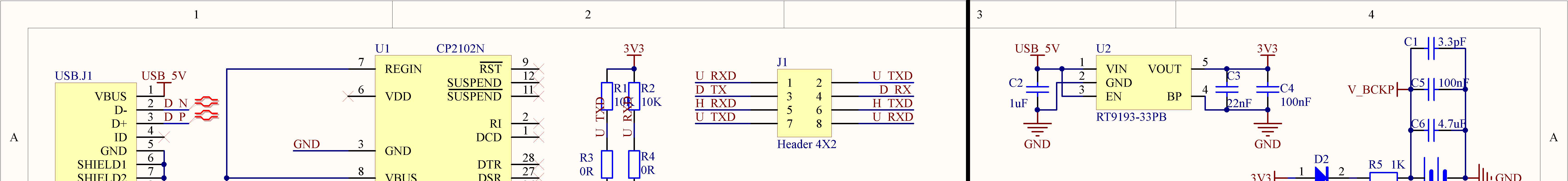
 Power supply: 5V input, RT9193 (3.3V), RT9166 (2.8V), and ML1220 backup battery. Image: Waveshare schematic
Low-Power Considerations
Section titled “Low-Power Considerations”- The module supports a backup mode activated via the WAKEUP pin. In backup mode, the module retains ephemeris data while drawing minimal current. Toggle the WAKEUP pin to return to active mode.
- For battery-powered applications, the < 40 mA draw at 5V (< 200 mW) is manageable, but refer to the Quectel LC29H datasheet for detailed power state specifications and sleep current figures.
Antenna
Section titled “Antenna”Requirements
Section titled “Requirements”The LC29H tracks L1 + L5 dual-band GNSS signals. The antenna must support both frequency bands:
| Band | Frequency | Constellations |
|---|---|---|
| L1 | 1575.42 MHz | GPS L1C/A, GLONASS L1, BeiDou B1I, Galileo E1 |
| L5 | 1176.45 MHz | GPS L5, BeiDou B2a, Galileo E5a |
The included antenna is an active (amplified) dual-frequency patch antenna. Using a single-band antenna will result in degraded accuracy and loss of L5 multipath rejection.
Connector
Section titled “Connector”- Type: IPEX 1st generation (U.FL compatible)
- Location: Right edge of the board (labeled “GPS” in the board photo)
- ESD protection: RCLAMP0531T.TCT clamp on the RF path
Placement Guidelines
Section titled “Placement Guidelines”- Clear sky view: Mount the antenna with an unobstructed view of the sky. GNSS signals do not reliably penetrate buildings, dense tree cover, or vehicles with metallized windshields.
- Ground plane: For best performance, mount the antenna on a metallic surface (ground plane) of at least 70mm x 70mm. The metal surface reflects signals upward into the antenna, improving gain.
- Orientation: Mount with the antenna label/patch facing the open sky (upward). The ceramic patch element receives signals from the hemisphere above it.
- Cable length: Keep the coaxial cable between the antenna and the IPEX connector as short as possible. Every meter of cable introduces signal loss at L-band frequencies.
- Interference sources: Maintain distance from WiFi antennas, cellular radios, and switching power supplies. The LC29H includes multi-frequency interference cancellation for WiFi/5G, but physical separation is always preferable.
SMA Adapter
Section titled “SMA Adapter”If your installation requires a panel-mount SMA connector or a different antenna with an SMA plug, use an IPEX-to-SMA pigtail adapter. Ensure the adapter and replacement antenna both support L1 + L5 dual-band operation.
Schematic Overview
Section titled “Schematic Overview”The HAT schematic shows the LC29H module connected through level-shifting circuitry to the Raspberry Pi GPIO header. Key sections:
Power Supply
Section titled “Power Supply”5V from the Pi GPIO header feeds the RT9193 (3.3V) and RT9166 (2.8V) LDO regulators. The ML1220 coin cell battery maintains RTC and ephemeris data when main power is removed.
GNSS Module
Section titled “GNSS Module”The LC29H module connects to the dual-frequency antenna via an RF path with integrated LNA and SAW filter. UART and I2C lines route through the jumper-selectable interface.
UART Interface and Level Shifting
Section titled “UART Interface and Level Shifting”The UART lines between the LC29H (2.8V logic) and the Raspberry Pi (3.3V logic) pass through an NDC7002N MOSFET-based level shifter. The I2C lines (SDA/SCL) use the same level-shifting approach with 4.7K pull-up resistors on both sides.
USB Bridge
Section titled “USB Bridge”The CP2102N USB-to-UART bridge provides the alternative USB connection path. When the jumper is at position A, UART traffic routes through this bridge to the micro-USB connector.
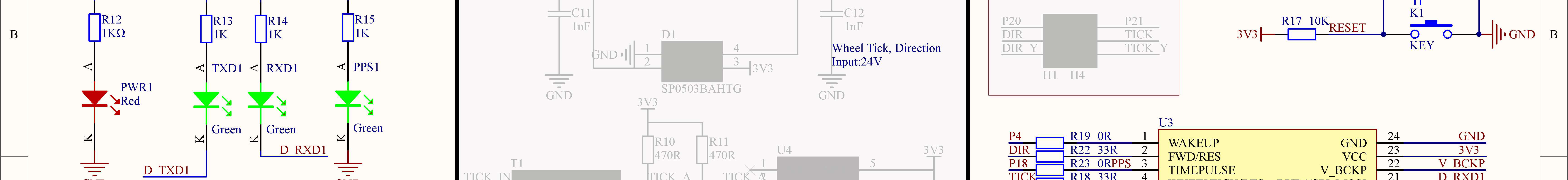
LED and Indicator Circuitry
Section titled “LED and Indicator Circuitry”All four status LEDs are driven through 1K series resistors. The schematic also shows the wheel tick/direction input path with ESD protection (SP0503BAHTG, rated for 24V inputs) and the RESET button circuit (10K pull-up, active-low tactile switch).
Full Schematic Pages
Section titled “Full Schematic Pages”Page 2 — Full circuit diagram

Page 3 — GPIO header and connector pinout
