Hardware Schematic
Full schematic for the Waveshare LC29H GPS/RTK HAT. Click any image to view at full resolution.
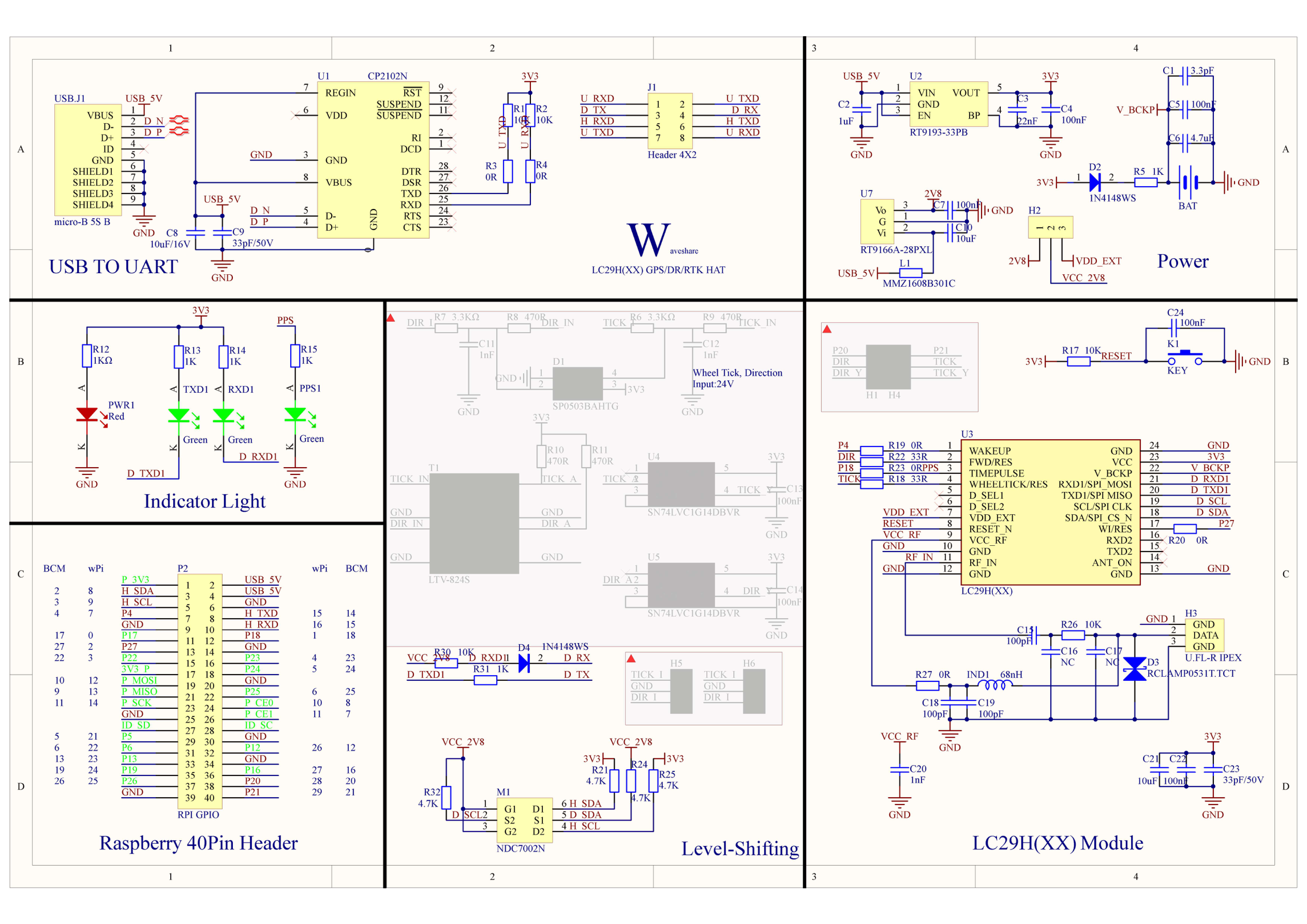
Circuit Diagram
Section titled “Circuit Diagram”Complete circuit showing the LC29H module, jumper-selectable UART/USB routing (positions A/B/C), CP2102N USB bridge, NDC7002N level shifters (2.8V ↔ 3.3V), I2C interface, LED indicators, power supply (RT9193 3.3V + RT9166 2.8V LDO regulators), ML1220 backup battery, and 40-pin GPIO header mapping.
Key sections
Section titled “Key sections”| Section | Location | Components |
|---|---|---|
| USB-to-UART bridge | Top-left | CP2102N, micro-USB connector, jumper position A |
| Power supply | Bottom-left | RT9193 (3.3V), RT9166 (2.8V), ML1220 battery |
| Level shifting | Center | NDC7002N MOSFETs, 4.7K pull-ups for I2C |
| GNSS module | Right | LC29H, IPEX antenna connector, ESD clamp |
| LED indicators | Top-center | PWR (red), TXD/RXD (green), PPS (green) |
| GPIO header | Center-right | 40-pin mapping, UART/I2C/PPS/RESET/WAKEUP |
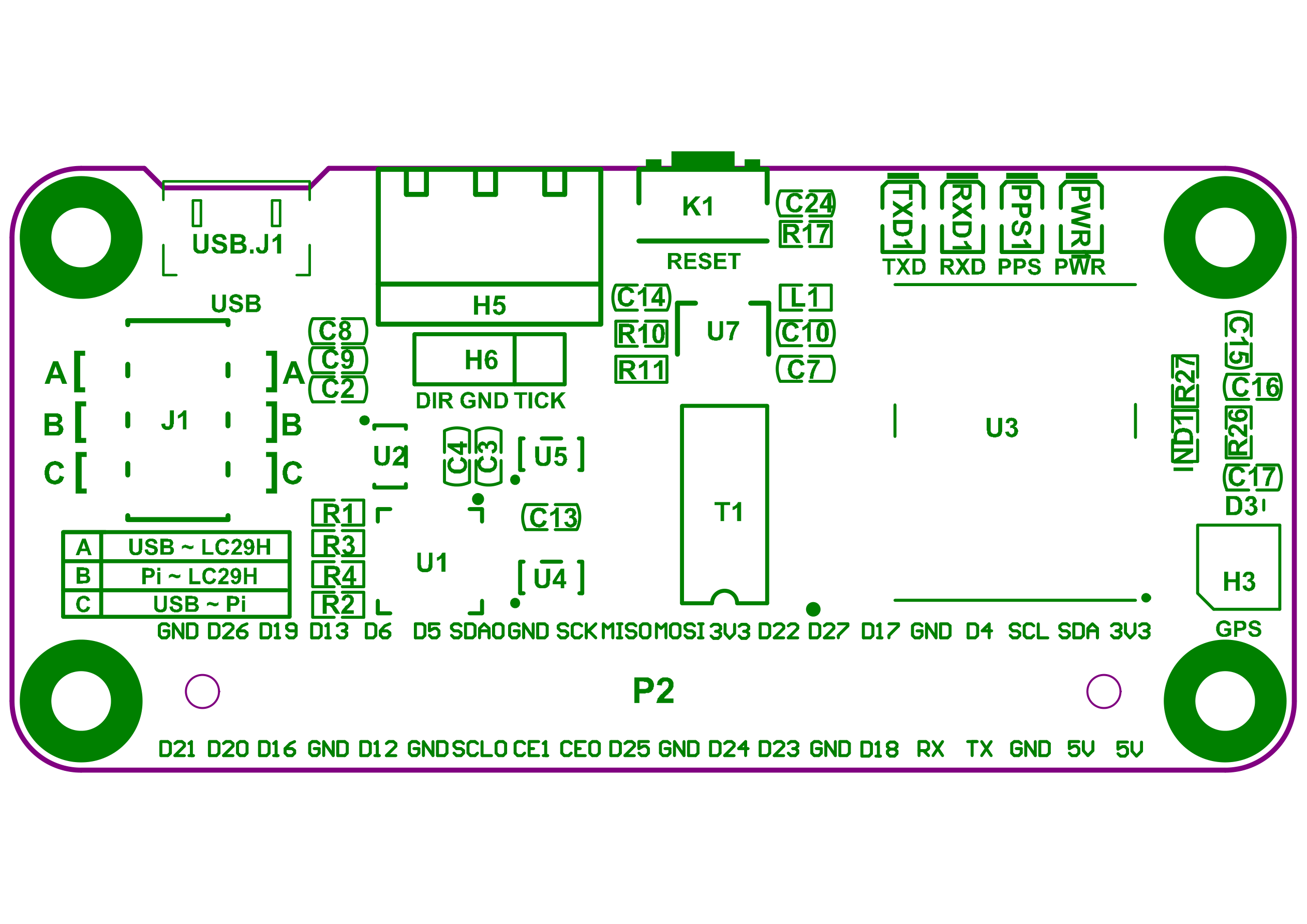
PCB Layout — Top
Section titled “PCB Layout — Top”Component placement on the front of the board. The LC29H module occupies most of the right side, with the USB connector and jumper block on the left.
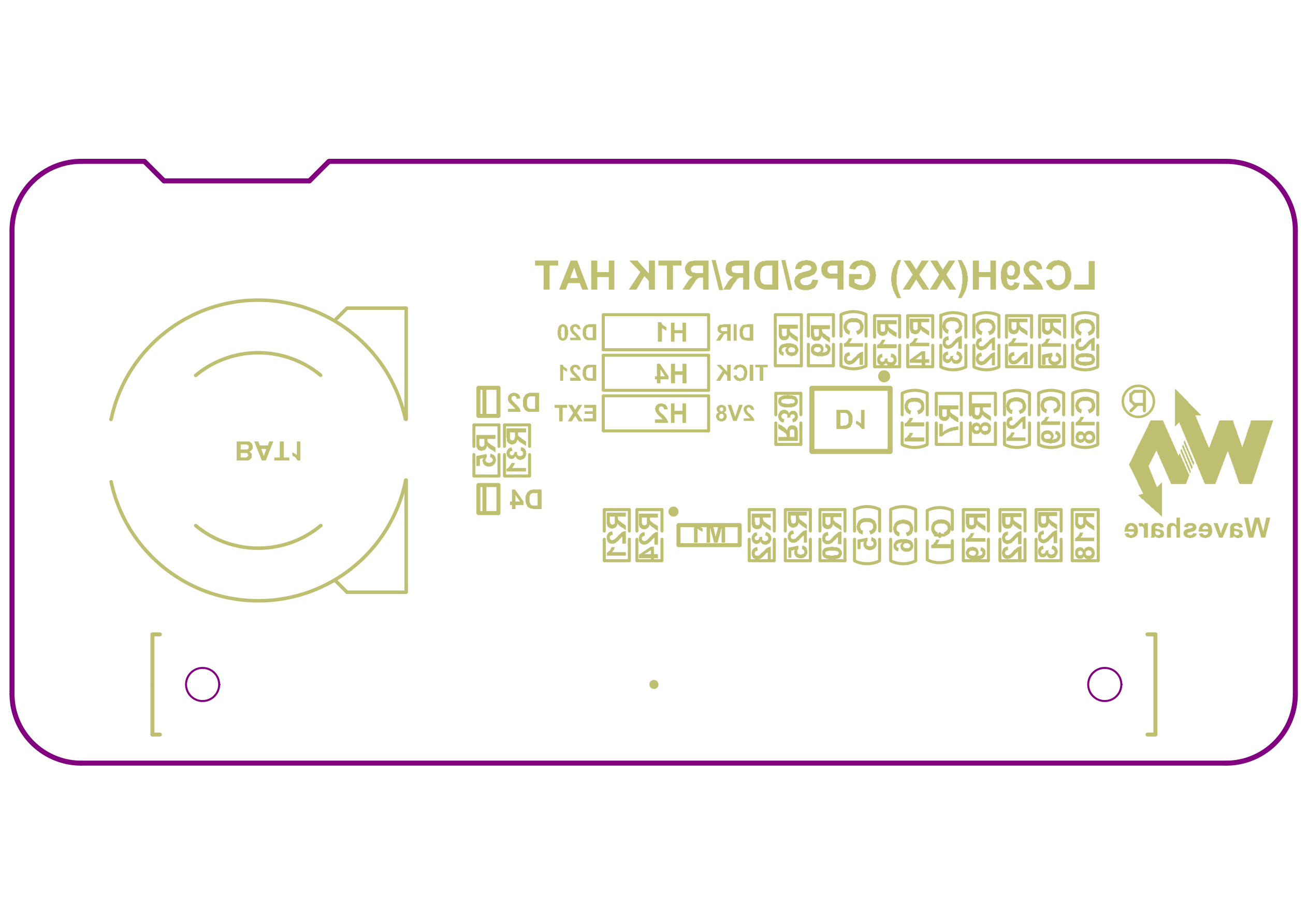
PCB Layout — Bottom
Section titled “PCB Layout — Bottom”Back side of the board showing the ground plane and passive components.
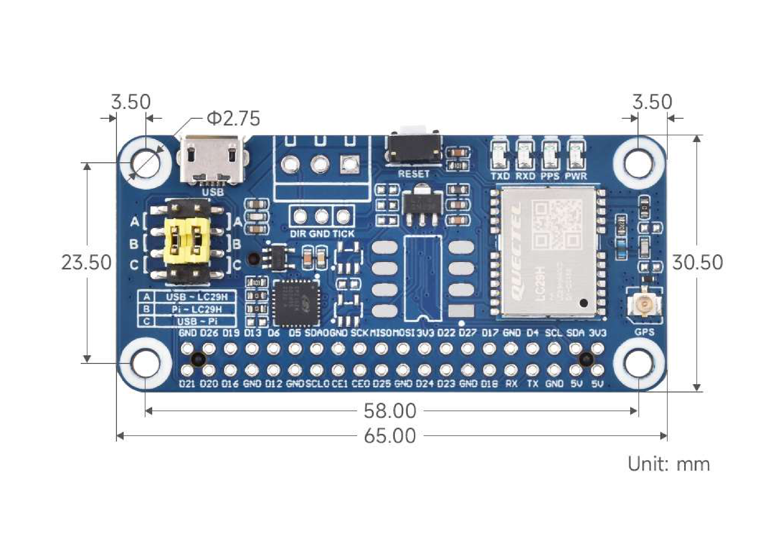
Board Dimensions
Section titled “Board Dimensions”Physical dimensions and mounting hole positions. The board is 65mm x 30.5mm, matching the Raspberry Pi HAT standard.