DR & RTK Application Note
1 Introduction This document describes the dead reckoning (DR) and real-time kinematic (RTK) features, including DR and RTK configurations and DR related messages for Quectel LC29H (BA), LC29H (CA) and LC29H (DA) modules. The features supported by each module are as follows: ⚫ LC29H (BA) supports DR and RTK. ⚫ LC29H (CA) only supports DR. ⚫ LC29H (DA) only supports RTK.
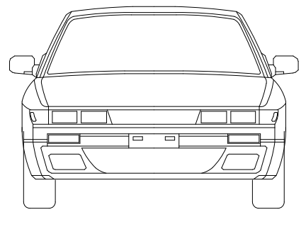
2 Configuration 2.1. DR Configuration 2.1.1. Orientation The LC29H (BA) and LC29H (CA) modules are designed to work on two-wheel or four-wheel vehicles. Both modules integrate an IMU as well as the GNSS receiver. Therefore, you must ensure that the device incorporating the module is firmly fixed to vehicle body. No relative movement is allowed between vehicle and device and maximum isolation from shock or vibration must be applied. Manually holding the device is not acceptable. The best way to guarantee good installation is to firmly screw the device down to the vehicle frame. Mounting location should permit easy access to power supply and GNSS antenna, and should not be exposed to excessive heat. Definitions of reference frame axes: ⚫ X-axis points towards the right of the vehicle. ⚫ Y-axis points towards the front of the vehicle. ⚫ Z-axis points towards the roof of the vehicle. Z Y X Figure 1: Reference Frame

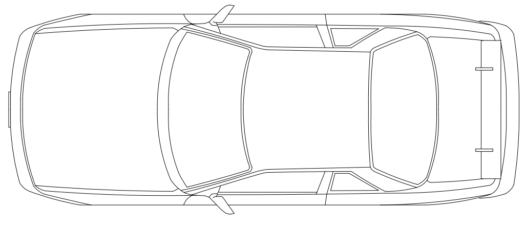
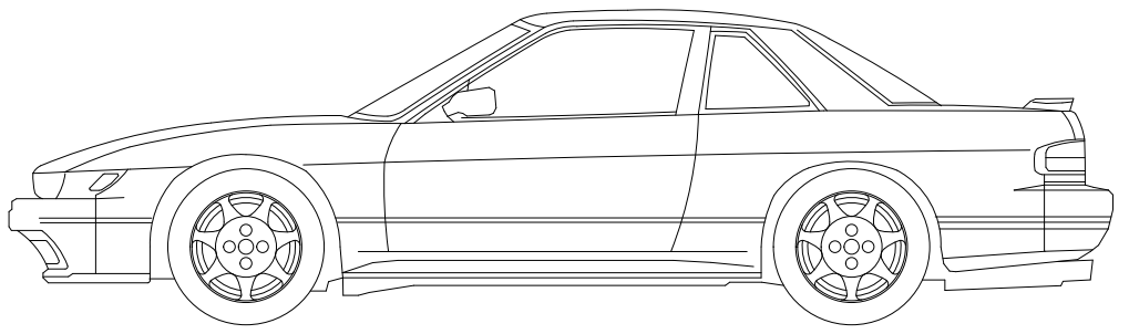
Module orientation is shown below: X Y Z Pitch Roll Yaw Figure 2: Module Orientation Firmly affix the device incorporating the module to vehicle body. Select a structurally sound location that is not prone to flexing (bending motion of vehicle chassis). 2.1.2. Mounting There are no mounting direction and angle limitations for mounting the Quectel LC29H (BA) or LC29H (CA) module on the vehicle. The reference model is as follows: NOTE
X Y Z Y Z Figure 3: Module Mounting Example 2.1.3. DR Calibration The module needs to be calibrated before the DR functionality will be useful. The DR calibration steps are as listed below: Step 1: Fix the device incorporating the module on the vehicle frame firmly. Any displacement, rotation or tilt of the device relative to vehicle plane, however small, may cause performance issues and/or void the calibration.
Step 2: Calibration should be performed under good GNSS signal and clear sky conditions. Step 3: Power up the module, then start the vehicle on a plain surface. Step 4: Drive at a speed of more than 3 m/s, and perform 3–4 turning movements. The module will start self-calibration, which would be completed in approximately 3 minutes. Step 5: The calibration process ends when <CalState> of $PQTMDRCAL message value is 2 (DR is fully calibrated). See Chapter 3.1.1 PQTMDRCAL for details about the message. After the calibration, there is no limit to driving trajectory and driving dynamics. You can perform verification tests in the following scenarios: 1) Open sky area, urban main road (high C/N0 levels). 2) Tunnels (assessment of DR performance during absence of satellite visibility). 3) Viaduct (assessment of DR performance during weak signal conditions). 4) Underground vehicle parking (DR performance during satellite signal absence). 5) Surrounding areas with dense buildings (occurrence of multi-path signals). 6) City boulevards (weak satellite signals). 7) Urban canyon (high multi-path signals with limited sky view). If the speed sensor of the vehicle is connected to the module, make sure that its precision is at least 0.05 m/tick. 2.2. RTK Configuration 2.2.1. RTCM Input Quectel LC29H (BA) and LC29H (DA) modules support the RTCM 10403.3 input messages listed in the table below. Table 1: Supported RTCM Input Messages Message Type Description 1005 Stationary RTK Reference Station ARP 1006 Stationary RTK Reference Station ARP with Antenna Height 1074 GPS MSM4 NOTE
Message Type Description 1077 GPS MSM7 1084 GLONASS MSM4 1087 GLONASS MSM7 1094 Galileo MSM4 1097 Galileo MSM7 1114 QZSS MSM4 1117 QZSS MSM7 1124 BDS MSM4 1127 BDS MSM7
3 DR Related Messages 3.1. PQTM Messages This chapter outlines the Quectel DR related PQTM (proprietary NMEA) messages supported by the Quectel LC29H (BA) and LC29H(CA) modules. 3.1.1. PQTMDRCAL Indicates the DR calibration state. Type: Output Synopsis: $PQTMDRCAL,<MsgVer>,<CalState>,<NavType>*<Checksum><CR><LF> Parameter: Field Format Unit Description <MsgVer> Numeric
Section titled “3 DR Related Messages 3.1. PQTM Messages This chapter outlines the Quectel DR related PQTM (proprietary NMEA) messages supported by the Quectel LC29H (BA) and LC29H(CA) modules. 3.1.1. PQTMDRCAL Indicates the DR calibration state. Type: Output Synopsis: $PQTMDRCAL,<MsgVer>,<CalState>,<NavType>*<Checksum><CR><LF> Parameter: Field Format Unit Description <MsgVer> Numeric”Message version. Fixed as 1. <CalState> Numeric
Section titled “Message version. Fixed as 1. <CalState> Numeric”DR calibration state. 0 = Not calibrated 1 = DR is lightly calibrated 2 = DR is fully calibrated <NavType> Numeric
Section titled “DR calibration state. 0 = Not calibrated 1 = DR is lightly calibrated 2 = DR is fully calibrated <NavType> Numeric”Navigation type. 0 = No position 1 = GNSS only 2 = DR only 3 = Combination Example: $PQTMDRCAL,1,0,1*5C
3.1.2. PQTMIMUTYPE Outputs the IMU type once after each boot-up. Type: Output Synopsis: $PQTMIMUTYPE,<MsgVer>,<Type>*<Checksum><CR><LF> Parameter: Field Format Unit Description <MsgVer> Numeric
Section titled “3.1.2. PQTMIMUTYPE Outputs the IMU type once after each boot-up. Type: Output Synopsis: $PQTMIMUTYPE,<MsgVer>,<Type>*<Checksum><CR><LF> Parameter: Field Format Unit Description <MsgVer> Numeric”Message version. Fixed as 1. <Type> Numeric
Section titled “Message version. Fixed as 1. <Type> Numeric”IMU type. 0 = IMU error 1 = LSM6DSR 2 = ICM-40608 3 = BMI160 4 = ICM-42670 Example: $PQTMIMUTYPE,1,2*52 3.1.3. PQTMVEHMSG Inputs/outputs vehicle information. Type: Input/output Synopsis: $PQTMVEHMSG,<MsgType>,<Timestamp>,<Par1>[,<Par2>,…,<ParN>]*<Checksum><CR><LF> Parameter: Field Format Unit Description <MsgType> Numeric
Section titled “IMU type. 0 = IMU error 1 = LSM6DSR 2 = ICM-40608 3 = BMI160 4 = ICM-42670 Example: $PQTMIMUTYPE,1,2*52 3.1.3. PQTMVEHMSG Inputs/outputs vehicle information. Type: Input/output Synopsis: $PQTMVEHMSG,<MsgType>,<Timestamp>,<Par1>[,<Par2>,…,<ParN>]*<Checksum><CR><LF> Parameter: Field Format Unit Description <MsgType> Numeric”Type of message input/output via UART interface. 1 = Vehicle speed (in m/s) 2 = Cumulative wheel tick
Field Format Unit Description 3 = Speeds of four wheels (in m/s) 4 = Cumulative wheel ticks of four wheels <Timestamp> Numeric Millisecond Timestamp since power-on. 32-bit unsigned integer. Always 0 when this message is input. <Par1> to <ParN> Numeric
Section titled “Field Format Unit Description 3 = Speeds of four wheels (in m/s) 4 = Cumulative wheel ticks of four wheels <Timestamp> Numeric Millisecond Timestamp since power-on. 32-bit unsigned integer. Always 0 when this message is input. <Par1> to <ParN> Numeric”Vehicle information. This field varies with the message type. See Chapter 3.1.3.1 If <MsgType> = 1 to 3.1.3.4 If <MsgType> = 4 for details. <MsgType> can only be 2 for LC29H (BA) and LC29H (CA) with software versions dedicated for two- wheel vehicles. Contact Quectel Technical Support for details about the software versions. 3.1.3.1. If <MsgType> = 1 Synopsis: $PQTMVEHMSG,1,<Timestamp>,<VehSpeed>*<Checksum><CR><LF> Parameter: Field Format Unit Description <Timestamp> Numeric Millisecond Timestamp since power-on. 32-bit unsigned integer. Always 0 when this message is input. <VehSpeed> Numeric m/s Speed. Range: -100 to 100. Result: Returns the input vehicle speed with timestamp: $PQTMVEHMSG,1,<Timestamp>,<VehSpeed>*<Checksum><CR><LF> Example: //Input: $PQTMVEHMSG,1,0,3.6*1C //Output: $PQTMVEHMSG,1,3748292,3.6*1D NOTE
3.1.3.2. If <MsgType> = 2 Synopsis: $PQTMVEHMSG,2,<Timestamp>,<WheelTickCNT>,<FWD_Ind>*<Checksum><CR><LF> Parameter: Field Format Unit Description <Timestamp> Numeric Millisecond Timestamp since power-on. 32-bit unsigned integer. Always 0 when this message is input. <WheelTickCNT> Numeric Tick Cumulative wheel ticks. <FWD_Ind> Numeric
Section titled “3.1.3.2. If <MsgType> = 2 Synopsis: $PQTMVEHMSG,2,<Timestamp>,<WheelTickCNT>,<FWD_Ind>*<Checksum><CR><LF> Parameter: Field Format Unit Description <Timestamp> Numeric Millisecond Timestamp since power-on. 32-bit unsigned integer. Always 0 when this message is input. <WheelTickCNT> Numeric Tick Cumulative wheel ticks. <FWD_Ind> Numeric”Forward/backward indicator. 0 = Invalid state 1 = Forward 2 = Backward Result: Returns the input cumulative wheel tick with timestamp: $PQTMVEHMSG,2,<Timestamp>,<WheelTickCNT>,<FWD_Ind>*<Checksum><CR><LF> Example: //Input: $PQTMVEHMSG,2,0,100,1*18 //Output: $PQTMVEHMSG,2,153954,100,1*27 1. When inputting cumulative wheel ticks through UART interface, make sure the input rate is at least 10 Hz. 2. For LC29H (BA) and LC29H (CA) with software versions dedicated for two-wheel vehicles: 1) Keep <FWD_Ind> always 1; 2) The input cumulative wheel tick with timestamp will not be output. Contact Quectel Technical Support for details about the software versions. NOTE
3.1.3.3. If <MsgType> = 3 Synopsis: $PQTMVEHMSG,3,<Timestamp>,<LF_Spd>,<RF_Spd>,<LR_Spd>,<RR_Spd>*<Checksum><CR><LF> Parameter: Field Format Unit Description <TimeStamp> Numeric Millisecond Timestamp since power-on. 32-bit unsigned integer. Always 0 when this message is input. <LF_Spd> Numeric m/s Left front wheel speed. Range: -100 to 100. <RF_Spd> Numeric m/s Right front wheel speed. Range: -100 to 100. <LR_Spd> Numeric m/s Left rear wheel speed. Range: -100 to 100. <RR_Spd> Numeric m/s Left rear wheel speed. Range: -100 to 100. Result: Returns the input speeds of four wheels with timestamp: $PQTMVEHMSG,3,<Timestamp>,<LF_Spd>,<RF_Spd>,<LR_Spd>,<RR_Spd>*<Checksum><CR><LF> Example: //Input: $PQTMVEHMSG,3,0,3.6,3.6,3.6,3.6*19 //Output: $PQTMVEHMSG,3,3748292,3.6,3.6,3.6,3.6*18 3.1.3.4. If <MsgType> = 4 Synopsis: $PQTMVEHMSG,4,<Timestamp>,<LF_TickCNT>,<RF_TickCNT>,<LR_TickCNT>,<RR_TickCNT><FW D_Ind>*<Checksum><CR><LF> Parameter: Field Format Unit Description <Timestamp> Numeric Millisecond Timestamp since power-on. 32-bit unsigned integer. Always 0 when this message is input.
Field Format Unit Description <LF_TickCNT> Numeric Tick Left front wheel tick count. <RF_TickCNT> Numeric Tick Right front wheel tick count. <LR_TickCNT> Numeric Tick Left rear wheel tick count. <RR_TickCNT> Numeric Tick Right rear wheel tick count. <FWD_Ind> Numeric
Section titled “Field Format Unit Description <LF_TickCNT> Numeric Tick Left front wheel tick count. <RF_TickCNT> Numeric Tick Right front wheel tick count. <LR_TickCNT> Numeric Tick Left rear wheel tick count. <RR_TickCNT> Numeric Tick Right rear wheel tick count. <FWD_Ind> Numeric”Forward/backward indicator. 0 = Invalid state 1 = Forward 2 = Backward Result: Returns the input cumulative wheel ticks of four wheels with timestamp: $PQTMVEHMSG,4,<Timestamp>,<LF_TickCNT>,<RF_TickCNT>,<LR_TickCNT>,<RR_TickCNT><FW D_Ind>*<Checksum><CR><LF> Example: //Input: $PQTMVEHMSG,4,0,100,100,100,100,1*03 //Output: $PQTMVEHMSG,4,153954,100,100,100,100,1*3C 3.1.4. PQTMSAVEPAR Saves the configurations set via $PQTM commands or $PAIR6010 into NVM. Reset the module after executing this command. Type: Command Synopsis: $PQTMSAVEPAR*<Checksum><CR><LF> Parameter: None
Result: ⚫ If successful, the module returns: $PQTMSAVEPAR,OK*72 ⚫ If failed, the module returns: $PQTMSAVEPAR,ERROR,<ErrCode>*<Checksum><CR><LF> Parameter: Example: $PQTMSAVEPAR*5A $PQTMSAVEPAR,OK*72 3.1.5. PQTMRESTOREPAR Restores all DR related configurations to default values. Type: Command Synopsis: $PQTMRESTOREPAR*<Checksum><CR><LF> Parameter: None Result: ⚫ If successful, the module returns: $PQTMRESTOREPAR,OK*3B ⚫ If failed, the module returns: $PQTMRESTOREPAR,ERROR,<ErrCode>*<Checksum><CR><LF> Field Format Unit Description <ErrCode> Numeric
Section titled “Result: ⚫ If successful, the module returns: $PQTMSAVEPAR,OK*72 ⚫ If failed, the module returns: $PQTMSAVEPAR,ERROR,<ErrCode>*<Checksum><CR><LF> Parameter: Example: $PQTMSAVEPAR*5A $PQTMSAVEPAR,OK*72 3.1.5. PQTMRESTOREPAR Restores all DR related configurations to default values. Type: Command Synopsis: $PQTMRESTOREPAR*<Checksum><CR><LF> Parameter: None Result: ⚫ If successful, the module returns: $PQTMRESTOREPAR,OK*3B ⚫ If failed, the module returns: $PQTMRESTOREPAR,ERROR,<ErrCode>*<Checksum><CR><LF> Field Format Unit Description <ErrCode> Numeric”Error code. 1 = Invalid parameters 2 = Failed execution
Parameter: Example: $PQTMRESTOREPAR*13 $PQTMRESTOREPAR,OK*3B 3.1.6. PQTMINS Outputs navigation results. Type: Output Synopsis: $PQTMINS,<Timestamp>,<SolType>,<Lat>,<Lon>,<Height>,<VEL_N>,<VEL_E>,<VEL_D>,<Roll>,<Pitc h>,<Heading>*<Checksum><CR><LF> Parameter: Field Format Unit Description <Timestamp> Numeric Millisecond Timestamp since power-on. 32-bit unsigned integer. <SolType> Numeric
Section titled “Parameter: Example: $PQTMRESTOREPAR*13 $PQTMRESTOREPAR,OK*3B 3.1.6. PQTMINS Outputs navigation results. Type: Output Synopsis: $PQTMINS,<Timestamp>,<SolType>,<Lat>,<Lon>,<Height>,<VEL_N>,<VEL_E>,<VEL_D>,<Roll>,<Pitc h>,<Heading>*<Checksum><CR><LF> Parameter: Field Format Unit Description <Timestamp> Numeric Millisecond Timestamp since power-on. 32-bit unsigned integer. <SolType> Numeric”Solution type. 0 = DR not ready. Roll and pitch ready. 1 = DR not ready. GNSS, roll, pitch, and relative heading ready. 2 = GNSS + DR mode. DR calibrated. 3 = DR only mode. <Lat> Numeric Degree Latitude. <Lon> Numeric Degree Longitude. <Height> Numeric Meter Height. <VEL_N> Numeric m/s Northward velocity. <VEL_E> Numeric m/s Eastward velocity. Field Format Unit Description <ErrCode> Numeric
Section titled “Solution type. 0 = DR not ready. Roll and pitch ready. 1 = DR not ready. GNSS, roll, pitch, and relative heading ready. 2 = GNSS + DR mode. DR calibrated. 3 = DR only mode. <Lat> Numeric Degree Latitude. <Lon> Numeric Degree Longitude. <Height> Numeric Meter Height. <VEL_N> Numeric m/s Northward velocity. <VEL_E> Numeric m/s Eastward velocity. Field Format Unit Description <ErrCode> Numeric”Error code. 1 = Invalid parameters 2 = Failed execution
Field Format Unit Description <VEL_D> Numeric m/s Downward velocity. <Roll> Numeric Degree Roll angle. <Pitch> Numeric Degree Pitch angle. <Heading> Numeric Degree Heading angle. Example: $PQTMINS,240951,1,31.82222216,117.11578436,62.555605,-0.004233,0.005535,- 0.004011,0.00,0.00,127.41*40 1. All angles are scaled from -180.0 to 179.9 with a wrap-around to 0.0 at +180.0. -180.0 = South, 180.0/0.0 = North, +90.0 = East, and -90.0 = West. 2. This message is only supported by LC29H (BA) and LC29H (CA) with software versions dedicated for two-wheel vehicles. Contact Quectel Technical Support for details about the software versions. 3.1.7. PQTMIMU Outputs the IMU raw data: acceleration, angular rate, and hardware wheel ticks. These values should match vehicle frame, see Figure 1: Reference Frame for details. Type: Output Synopsis: $PQTMIMU,<Timestamp>,<ACC_X>,<ACC_Y>,<ACC_Z>,<AngRate_X>,<AngRate_Y>,<AngRate_Z>,< WheelTickCNT>,<LastTick_Timestamp>*<Checksum><CR><LF> Parameter: Field Format Unit Description <Timestamp> Numeric Millisecond Timestamp since power-on. 32-bit unsigned integer. <ACC_X> Numeric m/s^2 Acceleration in X-axis direction. <ACC_Y> Numeric m/s^2 Acceleration in Y-axis direction. NOTE
Field Format Unit Description <ACC_Z> Numeric m/s^2 Acceleration in Z-axis direction. <AngRate_X> Numeric deg/s Angular rate in X-axis direction. <AngRate_Y> Numeric deg/s Angular rate in Y-axis direction. <AngRate_Z> Numeric deg/s Angular rate in Z-axis direction. <WheelTickCNT> Numeric Tick Cumulative wheel ticks. <LastTick_Timestamp> Numeric Millisecond Last tick timestamp. Example: $PQTMIMU,45454,-1.356730,-0.210568,9.757930,0.564879,0.549612,-0.412209,0,0*77 This message is only supported by LC29H (BA) and LC29H (CA) with software versions dedicated for two-wheel vehicles. Contact Quectel Technical Support for details about the software versions. 3.1.8. PQTMGPS Outputs the position status in GNSS only mode. Type: Output Synopsis: $PQTMGPS,<Timestamp>,<TOW>,<Lat>,<Lon>,<Altitude>,<Speed>,<Yaw>,<Accuracy>,<HDOP>,<PD OP>,<NumSatUsed>,<FixMode>*<Checksum><CR><LF> Parameter: Field Format Unit Description <Timestamp> Numeric Millisecond Timestamp since power-on. 32-bit unsigned integer. <TOW> Numeric Second Time of week. <Lat> Numeric Degree Latitude. NOTE
Field Format Unit Description <Lon> Numeric Degree Longitude. <Altitude> Numeric Meter Altitude. <Speed> Numeric m/s Ground speed (two-dimensional). <Yaw> Numeric Degree Heading of vehicle (two-dimensional). <Accuracy> Numeric Meter Horizontal accuracy estimate. <HDOP> Numeric
Section titled “Field Format Unit Description <Lon> Numeric Degree Longitude. <Altitude> Numeric Meter Altitude. <Speed> Numeric m/s Ground speed (two-dimensional). <Yaw> Numeric Degree Heading of vehicle (two-dimensional). <Accuracy> Numeric Meter Horizontal accuracy estimate. <HDOP> Numeric”Horizontal dilution of precision. <PDOP> Numeric
Section titled “Horizontal dilution of precision. <PDOP> Numeric”Position dilution of precision. <NumSatUsed> Numeric
Section titled “Position dilution of precision. <NumSatUsed> Numeric”Number of satellites used in navigation. <FixMode> Numeric
Section titled “Number of satellites used in navigation. <FixMode> Numeric”Fix mode. 0 = No fix 2 = 2D fix 3 = 3D fix Example: $PQTMGPS,86139,94183,31.82218794,117.11579022,65.755080,0.027,94.68,2.533952,0.555471,0.88 6183,29,3*6B This message is only supported by LC29H (BA) and LC29H (CA) with software versions dedicated for two-wheel vehicles. Contact Quectel Technical Support for details about the software versions. 3.1.9. PQTMCFGEINSMSG Sets/gets $PQTMINS, $PQTMIMU and $PQTMGPS message configurations. Type: Set/get Synopsis: //Set message configurations: $PQTMCFGEINSMSG,<Type>,<INS_Enabled>,<IMU_Enabled>,<GPS_Enabled>,<Rate>*<Checksum> <CR><LF> //Get message configurations: NOTE
$PQTMCFGEINSMSG,<Type>*<Checksum><CR><LF> Parameter: Field Format Unit Description <Type> Numeric
Section titled “$PQTMCFGEINSMSG,<Type>*<Checksum><CR><LF> Parameter: Field Format Unit Description <Type> Numeric”Set/get message configurations. 0 = Get 1 = Set <INS_Enabled> Numeric
Section titled “Set/get message configurations. 0 = Get 1 = Set <INS_Enabled> Numeric”Enable/disable the output of $PQTMINS message. 0 = Disable 1 = Enable <IMU_Enabled> Numeric
Section titled “Enable/disable the output of $PQTMINS message. 0 = Disable 1 = Enable <IMU_Enabled> Numeric”Enable/disable the output of $PQTMIMU message. 0 = Disable 1 = Enable <GPS_Enabled> Numeric
Section titled “Enable/disable the output of $PQTMIMU message. 0 = Disable 1 = Enable <GPS_Enabled> Numeric”Enable/disable the output of $PQTMGPS message. 0 = Disable 1 = Enable <Rate> Numeric Hz Set the output rate of $PQTMINS, $PQTMIMU or $PQTMGPS message. It can be 1, 2, 4, 5, 10. $PQTMGPS always outputs at 1 Hz even if configured to greater than 1 Hz. Result: ⚫ If successful, the module returns: $PQTMCFGEINSMSGOK*16 ⚫ If failed, the module returns: $PQTMCFGEINSMSGERROR*4A Example: //Set message configurations: $PQTMCFGEINSMSG,1,1,1,1,10*3F $PQTMCFGEINSMSGOK*16 //Get message configurations: $PQTMCFGEINSMSG,0*0E $PQTMEINSMSG,0,1,1,1,10*3E 1. Send $PQTMSAVEPAR*5A and reset the module for $PQTMCFGEINSMSG to take effect. 2. This command is only supported by LC29H (BA) and LC29H (CA) with software versions dedicated NOTE
for two-wheel vehicles. Contact Quectel Technical Support for details about the software versions. 3.1.10. PQTMVEHMOT Outputs vehicle motion information after DR calibration. Type: Output Synopsis: $PQTMVEHMOT,<MsgVer>,<PeakAcceleration>,<PeakAngularRate>*<Checksum><CR><LF> Parameter: Field Format Unit Description <MsgVer> Numeric
Section titled “for two-wheel vehicles. Contact Quectel Technical Support for details about the software versions. 3.1.10. PQTMVEHMOT Outputs vehicle motion information after DR calibration. Type: Output Synopsis: $PQTMVEHMOT,<MsgVer>,<PeakAcceleration>,<PeakAngularRate>*<Checksum><CR><LF> Parameter: Field Format Unit Description <MsgVer> Numeric”Message version. Fixed as 1. <PeakAcceleration> Numeric m/s2 Peak acceleration of vehicle. <PeakAngularRate> Numeric deg/s Peak angular rate of vehicle. Example: $PQTMVEHMOT,1,0.288124,0.159930*0A This message is only supported by LC29H (BA) and LC29H (CA) with software versions dedicated for four-wheel vehicles. Contact Quectel Technical Support for details about the software versions. 3.1.11. PQTMSENMSG Outputs sensor information. Type: Output Synopsis: $PQTMSENMSG,<MsgVer>,<TimeStamp>,<Par1>[,<Par2>,…,<ParN>]*<Checksum><CR><LF> NOTE
Parameter: Field Format Unit Description <MsgVer> Numeric
Section titled “Parameter: Field Format Unit Description <MsgVer> Numeric”4 = IMU sensor data matching vehicle reference frame. See Figure 1: Reference Frame for details. <TimeStamp> Numeric Millisecond Timestamp since power-on. 32-bit unsigned integer. <Par1> to <ParN> Numeric
Section titled “4 = IMU sensor data matching vehicle reference frame. See Figure 1: Reference Frame for details. <TimeStamp> Numeric Millisecond Timestamp since power-on. 32-bit unsigned integer. <Par1> to <ParN> Numeric”Sensor information. See Chapter 3.1.11.1 If <MsgVer> = 4 for details. 3.1.11.1. If <MsgVer> = 4 Synopsis: $PQTMSENMSG,4,<TimeStamp>,<IMU_Temp>,<IMU_GYRO_X>,<IMU_GYRO_Y>,<IMU_GYRO_Z>,< IMU_ACC_X>,<IMU_ACC_Y>,<IMU_ACC_Z>*<Checksum><CR><LF> Parameter: Field Format Unit Description <TimeStamp> Numeric Millisecond Timestamp since power-on. <IMU_Temp> Numeric Celsius IMU temperature. <IMU_GYRO_X> Numeric dps IMU X-axis gyro value. <IMU_GYRO_Y> Numeric dps IMU Y-axis gyro value. <IMU_GYRO_Z> Numeric dps IMU Z-axis gyro value. <IMU_ACC_X> Numeric g IMU X-axis accelerometer value. <IMU_ACC_Y> Numeric g IMU Y-axis accelerometer value. <IMU_ACC_Z> Numeric g IMU Z-axis accelerometer value. Example: $PQTMSENMSG,4,1977253,29.830917,1.727613,0.015743,0.804347,-0.250096,- 0.467039,10.444151*24
This message is only supported by LC29H (BA) and LC29H (CA) with software versions dedicated for four-wheel vehicles. Contact Quectel Technical Support for details about the software versions. 3.2. PAIR Messages This chapter explains DR related PAIR messages (proprietary NMEA messages defined by the chipset supplier). “P” means proprietary message, “AIR” means the command defined by the chipset supplier. 3.2.1. Packet Type: 6010 PAIR_CUSTOM_SET_MSG_OUTPUT Enables/disables the output of $PQTMDRCAL, $PQTMIMUTYPE, $PQTMVEHMSG, $PQTMVEHMOT and $PQTMSENMSG messages. Type: Set Synopsis: $PAIR6010,<Type>,<Output_State>*<Checksum><CR><LF> Parameter: Field Format Unit Description <Type> Numeric
Section titled “This message is only supported by LC29H (BA) and LC29H (CA) with software versions dedicated for four-wheel vehicles. Contact Quectel Technical Support for details about the software versions. 3.2. PAIR Messages This chapter explains DR related PAIR messages (proprietary NMEA messages defined by the chipset supplier). “P” means proprietary message, “AIR” means the command defined by the chipset supplier. 3.2.1. Packet Type: 6010 PAIR_CUSTOM_SET_MSG_OUTPUT Enables/disables the output of $PQTMDRCAL, $PQTMIMUTYPE, $PQTMVEHMSG, $PQTMVEHMOT and $PQTMSENMSG messages. Type: Set Synopsis: $PAIR6010,<Type>,<Output_State>*<Checksum><CR><LF> Parameter: Field Format Unit Description <Type> Numeric”Message type. -1 = Reset output state of all following sentence types to the default value 0 = $PQTMVEHMSG (Default: disabled) 1 = $PQTMSENMSG (Default: disabled) 2 = $PQTMDRCAL (Default: disabled) 3 = $PQTMIMUTYPE (Default: enabled) 4 = $PQTMVEHMOT (Default: disabled) <Output_State> Numeric
Section titled “Message type. -1 = Reset output state of all following sentence types to the default value 0 = $PQTMVEHMSG (Default: disabled) 1 = $PQTMSENMSG (Default: disabled) 2 = $PQTMDRCAL (Default: disabled) 3 = $PQTMIMUTYPE (Default: enabled) 4 = $PQTMVEHMOT (Default: disabled) <Output_State> Numeric”Message output state. 0 = Disabled 1 = Enabled Result: Returns $PAIR001 message. See document [1] protocol specification for details. NOTE
Example: $PAIR6010,0,1*0C $PAIR001,6010,0*0C 1. Send $PQTMSAVEPAR*5A and reset the module for $PAIR6010 to take effect. 2. The output rate of $PQTMVEHMSG and $PQTMSENMSG is always 10 Hz. The output rate of $PQTMDRCAL and $PQTMVEHMOT depends on position fix rate. $PQTMIMUTYPE is only output once after each boot-up. 3.2.2. Packet Type: 6011 PAIR_CUSTOM_GET_MSG_OUTPUT Gets whether the output of $PQTMDRCAL, $PQTMIMUTYPE, $PQTMVEHMSG, $PQTMVEHMOT and $PQTMSENMSG messages is enabled. Type: Get Synopsis: $PAIR6011,<Type>*<Checksum><CR><LF> Parameter: Field Format Unit Description <Type> Numeric
Section titled “Example: $PAIR6010,0,1*0C $PAIR001,6010,0*0C 1. Send $PQTMSAVEPAR*5A and reset the module for $PAIR6010 to take effect. 2. The output rate of $PQTMVEHMSG and $PQTMSENMSG is always 10 Hz. The output rate of $PQTMDRCAL and $PQTMVEHMOT depends on position fix rate. $PQTMIMUTYPE is only output once after each boot-up. 3.2.2. Packet Type: 6011 PAIR_CUSTOM_GET_MSG_OUTPUT Gets whether the output of $PQTMDRCAL, $PQTMIMUTYPE, $PQTMVEHMSG, $PQTMVEHMOT and $PQTMSENMSG messages is enabled. Type: Get Synopsis: $PAIR6011,<Type>*<Checksum><CR><LF> Parameter: Field Format Unit Description <Type> Numeric”Message type. 0 = $PQTMVEHMSG 1 = $PQTMSENMSG 2 = $PQTMDRCAL 3 = $PQTMIMUTYPE 4 = $PQTMVEHMOT Result: Returns $PAIR001 message and query result. See document [1] protocol specification for details. Query result message format: $PAIR6011,<Type>,<Output_State>*<Checksum><CR><LF> NOTE
Parameters included in the result: Field Format Unit Description <Type> Numeric
Section titled “Parameters included in the result: Field Format Unit Description <Type> Numeric”Message type. 0 = $PQTMVEHMSG 1 = $PQTMSENMSG 2 = $PQTMDRCAL 3 = $PQTMIMUTYPE 4 = $PQTMVEHMOT <Output_State> Numeric
Section titled “Message type. 0 = $PQTMVEHMSG 1 = $PQTMSENMSG 2 = $PQTMDRCAL 3 = $PQTMIMUTYPE 4 = $PQTMVEHMOT <Output_State> Numeric”Message output state. 0 = Disabled 1 = Enabled Example: $PAIR6011,1*11 $PAIR001,6011,0*0D $PAIR6011,1,0*0D This command is only supported by LC29H (BA) and LC29H (CA) with software versions dedicated for four-wheel vehicles. Contact Quectel Technical Support for details about the software versions. NOTE
4 Appendix A References Table 2: Related Document Table 3: Terms and Abbreviations Document Name [1] Quectel_LC29H&LC79H_Series_GNSS_Protocol_Specification Abbreviation Description ARP Antenna Reference Point BDS BeiDou Navigation Satellite System DR Dead Reckoning GLONASS Global Navigation Satellite System (Russian) GNSS Global Navigation Satellite System GPS Global Positioning System IMU Inertial Measurement Unit MSM Multiple Signal Message NMEA NMEA (National Marine Electronics Association) 0183 Interface Standard PQTM Proprietary Protocol of Quectel QZSS Quasi-Zenith Satellite System RTCM Radio Technical Commission for Maritime Services RTK Real-Time Kinematic
5 Appendix B Special Characters Table 4: Special Characters Special Character Definition <CR> Carriage return character. <LF> Line feed character. <…> Parameter name. Angle brackets do not appear in the message. […] Optional field of a message. Square brackets do not appear in the message. {…} Repeated field of a message. Curly brackets do not appear in the message. Underline Default setting of a parameter.